Super Sucking Siphon: Difference between revisions
| Line 16: | Line 16: | ||
* If the overflow outlet clogs, the breather pipe will fill, but will not overflow. | * If the overflow outlet clogs, the breather pipe will fill, but will not overflow. | ||
Siphon flow rate is a function of the | Siphon flow rate is a function of the internal radius of the siphon tube ('''r'''), times the square root of 2 times the constant of gravity ('''g''') times the head height ('''h'''): | ||
Most conventional HOB overflows have a 1 to 2 inch head. My water depth is 20" on my tank, giving me a head on 18". Therefore, my flow increased (from a 1" HOB) | Flow = πr<sup>2</sup> √(2gh) | ||
Most conventional HOB overflows have a 1 to 2 inch head. My water depth is 20" on my tank, giving me a head on 18". Therefore, my flow increased (from a 1" HOB) by a factor of ''4.25''! | |||
= Materials = | = Materials = | ||
Revision as of 14:04, 31 July 2007
Overview
This design is licensed under the GPL - if you build one, and sell or give it to someone else, you must also give them the complete assembly instructions, free of charge.
Introduction
I was unhappy with the flow rate of the overflows I have seen on the market, so I came up with this.
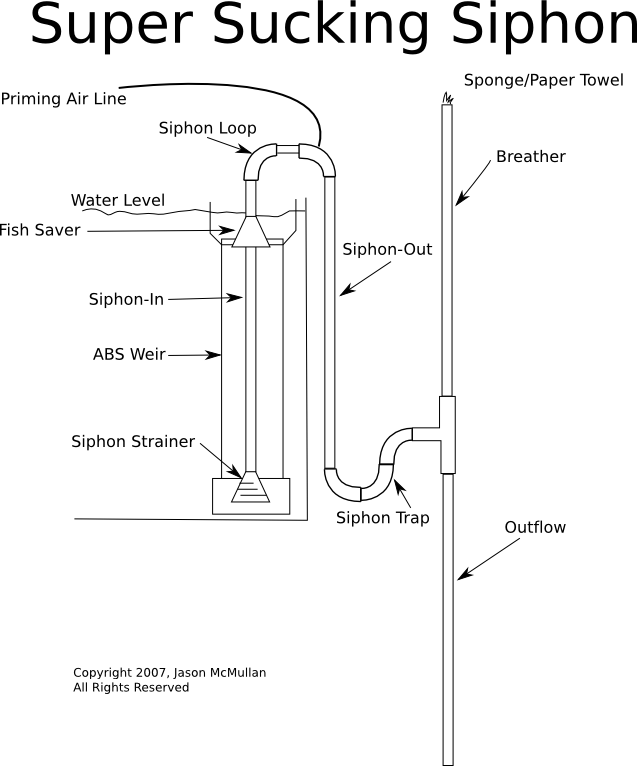
It's fail-safe reef hang-on-back overflow siphon that provides a lot of flow, but fails-safe:
- If the sump pump stops, the overflow weir prevents the entire tank from draining, and retains some water to allow the siphon to stay primed.
- If the overflow outlet clogs, the breather pipe will fill, but will not overflow.
Siphon flow rate is a function of the internal radius of the siphon tube (r), times the square root of 2 times the constant of gravity (g) times the head height (h):
Flow = πr2 √(2gh)
Most conventional HOB overflows have a 1 to 2 inch head. My water depth is 20" on my tank, giving me a head on 18". Therefore, my flow increased (from a 1" HOB) by a factor of 4.25!
Materials
- 10 ft (or so) of 3/4" CPCV pipe
- 3 ft (or so) of 1 1/2" ABS pipe
- 5 of 3/4" CPVC 90 degree elbows
- 1 of 3/4" CPVC tee
- 2 of 1" to 3/4" CPVC reduction joints
- 1 of 1 1/2" ABS cap
- 1 of 3" to 1 1/2" ABS reduction joint
- CPVC primer and cement
- ABS cement
Total cost: Less than $30 USD (2007 dollars)
Assembly Instructions
ABS Weir
The ABS weir will surround the overflow inlet, and prevent the tank from completely draining. ABS floats in seawater, and this design takes advantage of that fact.
First, measure the depth of your tank from your desired water line. If you want to have the maxium overflow pull, measure all the way to the glass on the inside of the tank. Otherwise, just measure to the substrate. Let's call that h.
Now, measure the height of the ABS 1 1/2" cap and the ABS 3" to 1 1/2" reduction joints. Let's call that a.
NOTE: ABS joints are 3/4", and we want to have 1/4" of the wier above the water line.
The length of ABS to cut is: cut length = h - a + 3/4" + 3/4" - 1/4"
The 1 1/2" ABS cap will be at the bottom of the weir, and must be cemented onto the bottom of the pipe.
The 3" to 1 1/2" ABS join will act at the overflow area. You don't have to cement it to the top of the pipe, and in fact, I recommend against it at this point.
You will need to make several 1/8" wide cuts around the wier, 2/3 of the cuts should be only 1/4" deep, and 1/3 should be 1/2" deep. Make it look like you could use it for an ashtray. The theory here is that the higher the water level, the more flow we want, until the 'critical point' of 1/4" above the maxiumum water line, when we want *all* of the area of the wier to pull in water.
If you have a different idea for the weir, feel free and try it out!
CPVC Siphon
This section is a little tricky, but if you make sure your cuts are correct, you will be fine.
Siphon Strainer
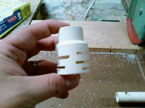
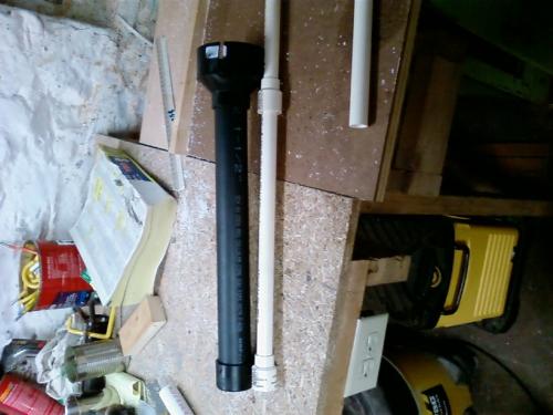
Take a 1" to 3/4" CPCV reduction joint, and hacksaw some 1/8" wide horizontal cuts in it, as depicted below.
Siphon Loop
Measure the height of the reduction joint. Call it r.
Measure the height from the top of your desired waterline to the top of your tank wall. Call it w
Cut three lengths of CPCV pipe.
- Siphon-In Pipe: cut length = h - r + 3/4" + w + 3/4"
- Siphon-Out Pipe: cut length = h - r + 3/4" + w
- Breather Pipe: cut length = h - r + 3/4" + w
Siphon-In Pipe
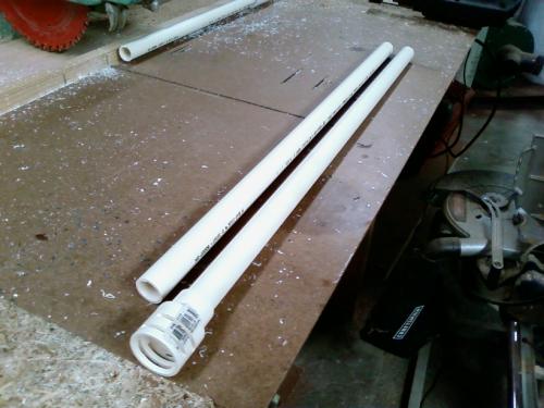
Force-fit the Siphon Strainer to the end of the Siphon-In pipe.
Using a round file, or similar tool, clear out the stop-ridge inside the second CPVC 1" to 3/4" reduction fitting, so that it will slip over the Siphon-In pipe. This fitting creats a 1/8" gap between itself and the ABS Weir, serving three functions:
- Prevents fish (greater than 1/8" in in width!) from getting sucked into the overflow
- Baffles any gurgling from the weir
- Prevents the Siphon-In tube from wobbling around in the weir.
See the photos below for an example of the finished assembly.
Siphon Loop
Use two of the 90 degree elbows and a 2" section of CPVC pipe to make a U out of the Siphon-In and Siphon-Out pipes.
Siphon Priming Air Line
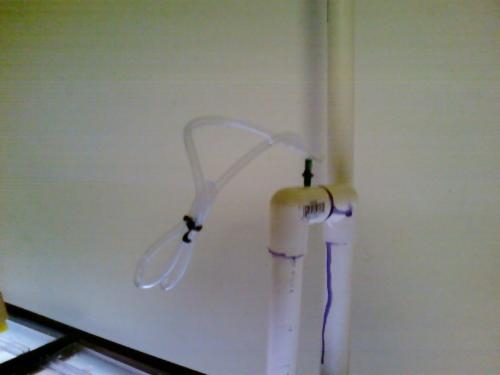
At this time, I recommend drilling a small hole and inserting an air line connector into the 90 degree elbow over the Siphon-Out pipe. This will allow you either to suck out air to prime the siphon once it's assembled.
NOTE: Those of you keeping score will notice that my breather in this picture is way too tall, and that the priming air line is over the wrong pipe. This is becuase you, dear reader, have just been spared a learning experience.
Siphon Trap
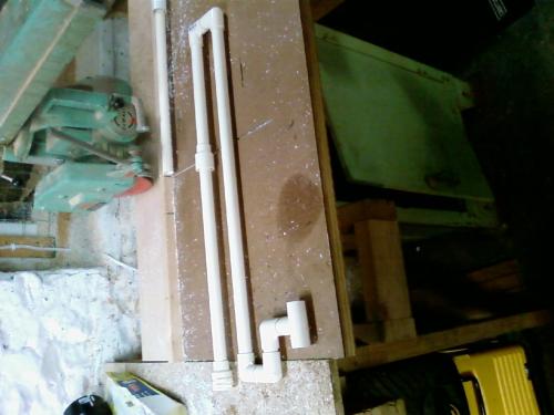
The siphon trap consists of three 90 degree CPVC joints, and one 3/4" CPVC tee, connected as in the diagram. You can get fancy and 'fold' them together as needed for your space requirements, but they will work in any case. I recommend using short 1 1/4" CPVC pipe segements to join these parts together.
Breather
Attach the breather to the top of the tee. This will pull in air to prevent the siphon from de-priming if the sump pump stops. It can get noisy, so I recommend that you put in a air-permiable sponge, or loosly stuff a paper towel in it. With a half of a paper towel sheet, I notice no noise from this setup.
Outflow
Use whatever plumbing you need for your system to hook the bottom of the tee to your sump/skimmer/refugium/whatever.
Wait
Wait for all the PVC solvent to cure, about 24 hours.
Installation Instructions
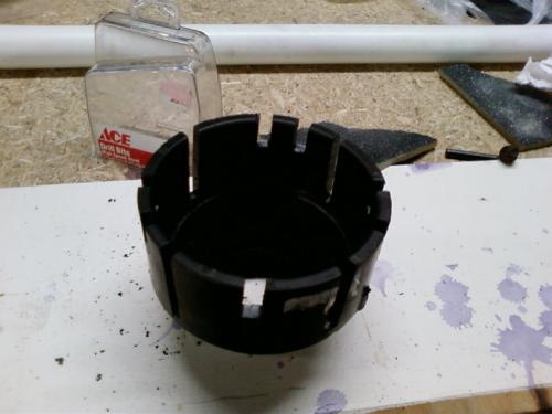
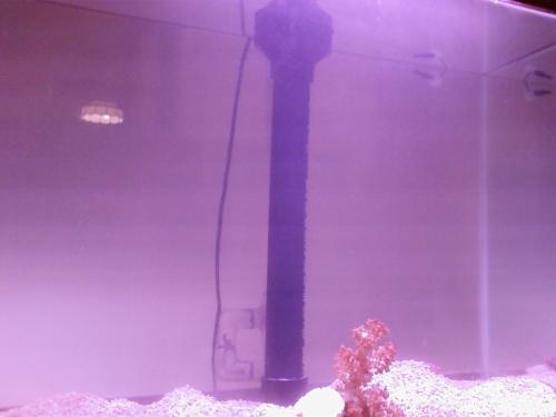
Place the Siphon Intake in the ABS Weir. Push the whole assembly into the tank, and let the wier fill with water. ABS just barely floats in salt water at 1.024 S.G, so you may want to use some spare rocks to keep it in place. See the picture below for my full-height setup.
The big black thing is the ABS Weir. You can just barely see the CPVC Siphon Trap behind it.
Connect the outflow to your sump/skimmer/refugium/whatever. My setup generates a lot of bubbles, so I send it all to the skimmer first.
Prime the siphon by closing the outflow, putting your hand over the breather, and sucking out the air. (You did wait for the solvent to cure, right? Otherwise, you (and your reef) have just started sucking down some nasty neurotoxins).
Clamp the siphon priming air hose closed, and enjoy the flow.
